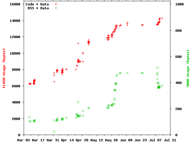
Figure 1: RAM and ROM usage over the development period.
This started in December 2006 while Christmas shopping. I saw a Mathmos aduki, a pebble-like device that slowly changed colour. The aesthetics of this thing were astounding, although I couldn't help but wonder if it was hackable to make some form of ambient device to indicate something meaningful though its colour.
Unfortunately the aduki seemed somewhat too expensive to buy for the purpose of dismantling and possibly breaking. It also appeared to use a simple light and colour wheel to provide its tranquil colour transitions, and so wouldn't be easy to commandeer for my purposes. Still, this had got me thinking, and so I started researching ambient devices to see what was out there.
I quickly found Ambient Devices Inc. who sell a variety of products and also an interesting looking 'datacast decoder', as well as the Nabaztag WiFi rabbit. The Ambient Devices looked cool, but somewhat expensive and limited only to areas that have wireless coverage, which is mainly the US. Nabaztag looked cool, very hackable, but expensive and a lot of the technical documentation was in French.
Searching around further I found a great page about Thomas Driemeyer's Computer Controlled LED Lamp. This looked good, almost exactly what I wanted, although used RS232 to control the device so would need a computer to allow the device to display changing information. Apart from this, the choice to use an Atmel AVR microcontroller, a nifty 8-bit RISC chip that had been sourced from Tuxgraphics was a good one. This led me onto the AVR web server devices which would perfectly allow me to control a LED Lamp, but using Ethernet for connectivity.
At this point I was pretty sure what I wanted to do. I wished to use a Tuxgraphics kit to make an Internet connected LED Lamp.
I started prototyping the software on one of Tuxgraphics single sided AVR Ethernet kits. Initially I worked on just getting the Ethernet device working, and setting up a single PWM output. Once this was proven, I start looking at implementing various bits of code to enable control of the device.
The software is written in ANSI C99, supported by AVR libc. I chose not to use a RTOS since I thought it would not be needed and would waste space (the device has only 1K SRAM). Instead I added an event module that allows flags to be set in a register to indicate that some action needs servicing, which when combined with a timer module, allows events to be scheduled for some point in the future. A main loop similar to the following was enough to support all the application code, without the need for an RTOS or context switching:
    do
    {
        if(M_EventIsSet(EV_ETH))
        {
            M_EventClr(EV_ETH);
            ....
        }

        if(M_EventIsSet(EV_TIMER_DHCP_RENEW))
        {
            M_EventClr(EV_TIMER_DHCP_RENEW);
            ....
        }

        /* Enable sleep */
        SMCR = (1<<SE);

        /* Start sleeping if no events posted */
        if(EVENT_REG == 0) __asm volatile ("sleep" ::);
    }
    while(1);
Listing 1: Program main loop.
The code checks for any events and then starts the sleep procedure. If an interrupt occurs and sets an event, it must both set a bit in EVENT_REG and prevent sleeping by clearing the SE bit in SMCR to ensure that the main loop does not start sleeping once the interrupt has completed. EVENT_REG is #defined as GPIOR0, one of the general purpose registers provided in the ATmega88/168. This is a bit-addressable register in IO space, which enables bits to be atomically set and cleared using the sbi and cbi instructions, hence avoiding typical read-modify-write operations or volatile specifiers that would require interrupts to be disabled when updating a shared context variable. This makes event manipulation code efficient and compact.
I also decided not to use a memory allocator such as malloc. The device has only 1K of SRAM, and it seemed that there were few places that would need dynamic memory. Instead, where persistent data was essential, I made a few small tables in RAM dimensioned to the worst case usage. For example, the ARP cache and IP routing table are small structures in RAM using bespoke allocators which typically don't require any extra RAM or structures to manage.
For temporary memory allocations I used the stack with a particular design pattern to help ensure large structures are short lived. For example, when reading a packet from the Ethernet device, the code is much simpler and more compact if the whole header can be read at once. I therefore define structures to match packet headers and read the data into an instance of the required structure allocated on the stack. To ensure that undesired fields or redundant fields such as checksums do not persist on the stack beyond their useful lifespan, I would use a small function to read the header and return any longer lived parameters to the calling function.
static uint16_t __attribute__ ((noinline)) readPacket(udpparam_t *const udpp)
{
    udpheader_t hdr;

    /* Read header */
    enc28j60RxPktRead(sizeof(udpheader_t), &hdr);

    /* Save useful parameters */
    udpp->sport      = ntohs(hdr.sport);
    udpp->payloadLen = ntohs(hdr.length) - sizeof(udpheader_t);

    ...

    return ntohs(hdr.dport);
}

void UdpProcessPacket(void)
{
    udpparam_t udpp;

    switch(readPacket(&udpp))
    {
        case UDP_PORT_BOOTPC:
            DhcpProcessPacket(&udpp);
            break;
        case UDP_PORT_NETBIOS_NS:
            NetBiosNsProcessPacket(&udpp);
            break;
       ....
    }
}
Listing 2: Temporary usage of the stack.
Listing 2 shows such a function for UDP processing. In this case the stack saving at the point where DhcpProcessPacket() or NetBiosNsProcessPacket() are called is the difference in the size of udpheader_t and udpparam_t, in this case 50% of the header size, or 4 bytes. For TCP the saving is slightly more at 8 bytes. An important thing to note is that readPacket() has been attributed with noinline. This tells GCC not to inline the function, as otherwise the code could end up increasing stack usage since UdpProcessPacket() may require a stack frame large enough to hold both structures.
Finally, where possible, I would have liked to encourage tail call optimisation by the compiler. This is an optimisation whereby the current stack frame is disposed prior to calling a child function, thus reducing stack nesting. Most commonly it is used to flatten recursive functions into iterative equivalents, but can usually be applied to functions where it is safe to dispose the stack frame prior to calling some desendant function whose return value is either returned directly or ignored.
#include <stdint.h>

/* Prototype */
uint8_t lookup(uint16_t val);

/* Example function */
uint8_t func(uint8_t a)
{
    uint16_t r = 0;
    uint8_t  t;

    for(t = 1; t <= a; t++)
    {
        r += t;
    }

    return lookup(r);
}
Listing 3: Contrived example where tail optimisation maybe performed.
Listing 3 shows a function that could make use of the stack before calling a function whose result is directly returned. Assuming that r and t resulted in stack usage and were not optimised into registers, the compiler may spot that the stack can be restored prior to calling lookup() and replace the call to lookup() with a jump. In such a case, lookup() would run on a smaller stack, and return directly to the caller of func() itself, saving the instructions required to return through func(). Unfortunately AVR-GCC 4.1.2 doesn't seem to apply any tail call optimisation, even in trivial examples such as the following listing.
    #include <stdint.h>

    /* Prototype */
    uint8_t lookup(uint8_t val);

    /* Example function */
    uint8_t func(uint8_t a)
    {
        return lookup(a*2);
    }
    /* END OF FILE */
|
.global func
    .type   func, @function
func:
/* prologue: frame size=0 */
/* prologue end (size=0) */
    lsl r24
    rcall lookup
    clr r25
/* epilogue: frame size=0 */
    ret
/* epilogue end (size=1) */
|
Listing 4: Simple function and output when compiled with avr-gcc -03 -S.
In this example, the clr r25 and ret could both be removed if the rcall was changed to an rjmp. The clr is to ensure that the return result is an unsigned 8 bit value as per the function declaration, but the prototype for lookup() should make it apparent to the compiler that this is redundant.
8-bit timers are used to drive each output channel of the LED lamp, giving independent control of red, green and blue. The timers are configured in fast PWM mode, repeatedly counting from 0 to 255 at a rate of one step every 8MHz tick. The comparator register for each timer is set to a value between 0 and 255 to range from fully off to full intensity output. Extra code manages enabling and disabling the timer hardware blocks via the Power Reduction Register to save power when all outputs are 0.
To enable changes in the light output to be sequenced, a different timer is configured to generate an interrupt once every 4 milliseconds. This drives the light sequencer which interprets a stream of control bytes to determine the PWM output settings. Bresenham's line drawing algorithm is used when fades from one intensity to another are desired such that PWM output can be smoothly changed over a number of 4ms steps. This timer is also stopped to save power under some conditions, such as the end of the instruction stream being reached.
Ideally I wanted something that would self configure and start when plugged into a LAN, preferably without the need of a controlling PC. Research led me to Zeroconf which looked like it would be a good set of standards to follow, and so I decided to implement various parts of the following standards to get the device started:
| Protocol | RFC | Implemented Subset |
|---|---|---|
| ARP | rfc826 | No ageing of cache entries (but ARP table is tiny). |
| IPv4 | rfc791 | Reassembly/defragmentation missing, TOS and any options ignored. |
| Auto IP | rfc3927 | Optional address defence omitted. |
| BOOTP | rfc951 | Only enough to support DHCP. |
| DHCP | rfc2131 | Discovery and assignment only, no reuse case. |
| ICMP | rfc792 | Only echo request/response (ping). |
| UDP | rfc768 | No UDP checksum generation/verification. |
| TCP | rfc793 | Only implements client sockets. Fixed receive window, no handling for Urgent data. |
| NetBIOS | rfc1001, rfc1002 | Only decodes and response to NBNS requests for the host. |
| HTTP | rfc1945 | Can send a GET request with Host: field, and skip HTTP header on response. |
Table 1: Summary of implemented protocols and omissions.
This is enough to get the device connected to a LAN and on the Internet if DHCP provides a router configuration. There is however no service discovery protocol in the list, meaning that it is difficult to detect and communicate with the device, although broadcast pings to its subnet could be used as a very poor method of discovery. Better service discovery options are mDNS/DNS-SD and uPNP. mDNS looked promising, but Windows support seemed uncertain, while uPNP looked a little complicated and poorly specified. Hence I decided to implement a subset of NetBIOS/NBNS to enable the device to be addressed by a text name.
I chose to give the device the NetBIOS name 'lightbulb', and once configured, typing "ping lightbulb" automatically resolves its address and pings the device, largely solving the discovery problem for my needs. This however still missed a method for controlling the LED light output.
I developed a simple instruction format that allows for sequencing changes in the light output. The instructions are byte based, and the count of leading 1's on each variable length instruction determines how it should be decoded. A small interpreter runs on the device to interpret the instruction sequences and modify the light output accordingly (this is implemented in seq.c).
Instruction sequences can be simply constructed in C code by using a number of macros depending on the commands required, as shown in the following example:
#include "seq.h"

uint8_t seq =
{
    M_SeqCmdRgb(0, 0xff, 0x00, 0x00),
    M_SeqCmdDelayMs(333),
    M_SeqCmdRgb(0, 0x00, 0xff, 0x00),
    M_SeqCmdDelayMs(333),
    M_SeqCmdRgb(0, 0x00, 0x00, 0xff),
    M_SeqCmdDelayMs(333),
    M_SeqCmdRgb(0, 0x00, 0x00, 0x00),
    M_SeqCmdStop()
};
Listing 5: Source code to construct a red, green, blue sequence.
The full list of commands is defined in seq.h and includes commands to access one of 4 'registers' together with jumps, conditional jumps and simple arithmetic operations. The most powerful command is however the 'read web' instruction:
#include "seq.h"

uint8_t seq =
{
    /* Command and IP address */
    M_SeqCmdReadWeb(64, 233, 183, 147),

    /* Length and host from which to fetch */
    14, 'w', 'w', 'w', '.', 'g', 'o', 'o', 'g', 'l', 'e', '.', 'c', 'o', 'm',

    /* Length and page to fetch */
    1,  '/',

    /* Sequence to execute should HTTP fetch fail */
    M_SeqCmdStop()
}
Listing 6: Source code to construct a HTTP fetch command.
This command causes the device to make a TCP connection to the specified IP address and make a HTTP request for the given page. Since the device has no DNS client, both the IP address and host name need to be supplied such that the HTTP query can correctly send the Host: field in the request header to enable access to content on servers sharing IP addresses. If the request is successful, the received data replaces the currently executing commands and be automatically executed. If unsuccessful execution will continue, and in this example, stop, although I normally add commands to implement some colour sequence followed by a delay and jump to retry the fetch.
Instruction sequences are stored on the device's EEPROM, but more usefully can be sent to the device via UDP packets on port 8888. Packets sent to the device cause the new instruction sequence to immediately start executing, while the EEPROM sequences are triggered by specific events such as the Ethernet lead being inserted or removed. One predefined sequence is executed after successful configuration of the device. This sequence can be used for bootstrapping if appropriate commands are specified to fetch a command sequence via HTTP.
Where possible I developed code on the PC and then ported it to the microcontroller. The stdint.h types simplified this somewhat by ensuring that variables were consistently sized between platforms. I also once used AVR Studio 4.12 to run code on an AVR emulator, although found AVR Studio to be a little buggy, for example requiring watch windows to be manually refreshed in some confusing situations. AVR Studio is however a free download from Atmel, so not at all bad. I do hope they continue to release it for free and improve it though.
A lot of the protocol development was initially performed on the microcontroller board to use the Ethernet device. This caused a number of problems, mainly being the lack of output from the device and the inability to examine the running program as I have no debugger. The limited erase/write cycles of the AVR flash device also concerned me and so I decided to develop more code on the PC. To accomplish this, I needed to simulate the Ethernet device on the microcontroller board. Ideally I would have used a raw packet socket on Windows, but this can't easily be done. To workaround this I decided to use WinPcap which presents a simple API to send and receive raw packets on Windows. With a little work, a couple of POSIX threads, mutexes and condition variables, I was able to implement a replacement for the enc28j60 module I wrote for the microcontroller device with one that gave an identical API on the PC.
At this point I found that my LAN didn't work very well with two devices connected to a single Ethernet port. I suspect that the switch to which the PC was connected was having trouble seeing two MAC addresses appearing on a single port. So I decided to install the free VMWare Player which provides virtual Ethernet devices to enable VMs to network. I found that WinPcap was happy to open the virtual network adaptors and could communicate freely, both to the Virtual Machine, the VMware DHCP server and with correct configuration, the Internet. WireShark was also happy to observe all packets sent and received on the virtual network device enabling me to determine what the device was doing.
Finally I was able to run my code as standalone executables on the PC, using the VMWare network to host the device, Wireshark to watch the traffic, and using any PC tools I wanted to debug the firmware. Being able to use terminal output and GDB greatly accelerated protocol development.
The following tables shows the size of each firmware module.
|
| ||||||||||||||||||||||||||||||||||||||||||||||||||||||||||||||||||||||||||||||||||||||||||
Table 2: Size of firmware by module, in bytes. | |||||||||||||||||||||||||||||||||||||||||||||||||||||||||||||||||||||||||||||||||||||||||||
Code is stored in the text section, while initialised data and strings are stored in data. BSS represents zero-initialised variables and structures. Therefore FLASH is consumed by both text and data, while SRAM is used by both bss and data due to the Harvard architecture of the AVR. The slight exceptions are eprom.o where the data is stored in the EEPROM, and data declared with PROGMEM which exists only in FLASH but has to be specially accessed since it is not addressible in the data memory space.
From the table, the total text is 14208, total data is 269, and total bss 302 bytes. This means that 14477 bytes of FLASH, 375 bytes of SRAM, and 196 bytes of EEPROM are used in total from this build.
My Makefile also keeps a log of the total image size against build time. For memory constrained systems I find this a useful way of checking how much memory is being used during development, and Figure 1 is a graph of the raw data showing the growing FLASH and SRAM consumption. It can clearly be seen that the code has out grown the ATmega88, and requires most of the 16K of FLASH in the ATmega168.
Figure 1: RAM and ROM usage over the development period.
Initially I started with a basic Tuxgraphics Ethernet board, and a small circuit to drive a pair of Kingbright N63AX tri-colour LEDs I picked up at Maplin. This was great and got me started on the project, but had a couple of problems. The first was that the circuit board was too large for my housing, and the second was that the LM2937 voltage regulator was getting uncomfortably hot when running from 9 volts.
I wanted a 9 volt source to allow each colour pair of the LEDs to be ran in series, so wasn't keen on changing that. I checked the current being drawn by the microcontroller and Ethernet devices, and discovered that the ec28j60 was drawing around 140mA. This is in spec with the datasheet, but seemed a lot when compared with the microcontroller that was drawing almost nothing. I then used the National Instruments site to calculate the temperature rise and required heat sinking for the LM2937. I'm still not sure if it was correct or not, but given the voltage drop (9.0 to 3.3v) and the current, it would need quite a large heat sink and operate at 125°C. At this point I decided it would just be better to use a more efficient regulator rather than waste the power or sacrifice more space for a heatsink. So, researching switching regulators, I came across Dimension Engineering who sold a 3.3V 1A switching voltage regulator, packaged to be a drop in replacement for the LM2937! I ordered one of these which cost $15 + $1.25 dollars for international delivery, and a while later I had it in my circuit replacing the old regulator and operating with virtually no noticeable temperature increase.
 |
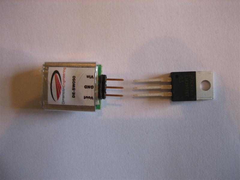 |
| Original circuit board. Note the small heatsink on the LM2937. | Replacement and original regulator (Note: This shows a SW050, but the replacement part is actually a DE-SW033). |
To fix the space problem I started considering manufacture of a PCB. Looking around, it seemed that a number of places would do small runs of PCBs, BatchPCB appearing to be reasonably priced with a helpful website. They recommended using Eagle to layout the circuit, so I downloaded the trial version and started entering the circuit. This package has quite a steep learning curve, and the component library isn't very well organised; it also omitted a number of the parts I needed such as the Magjack and enc28j60 IC. Having struggled with Eagle for a number of weeks, I rechecked the Tuxgraphics shop and found that they were now selling a PCB version of the microcontroller circuit I had already purchased. This also had a slightly larger Atmega168 (16k flash as opposed to the 8 of the Atmega88) on it, which was useful as the software was starting to grow at that point. I quickly ordered the Tuxgraphics PCB version of the circuit and threw away my Eagle files. With a little filing, I worked out that the PCB fitted my housing, and I was ready to start construction.
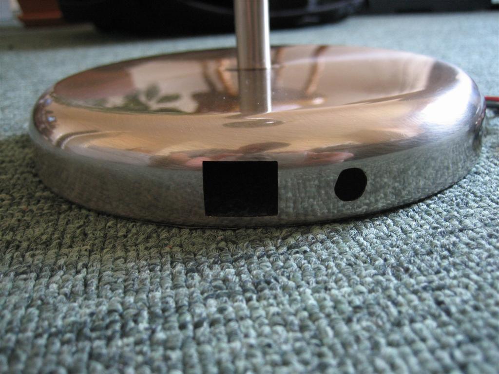
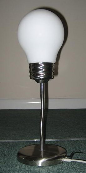
The housing was to be made from an old lamp that I had received as a gift a number of years ago. It was in the shape of a lightbulb with a large nut holding a concrete or cement block in the base to make it stable. The upper glass dome is frosted, and held in place by a springy metal clip. Dismantling the old lamp was easy, and was done without damaging any parts. The change I made to the lamp was to enlarge the existing cable outlet in the base and make it square to hold the Ethernet jack. This was done by carefully masking the area and then using a set of metal files to remove the excess metal until the desired opening was made. After that I drilled an 8mm hole to accept a panel mount DC jack for the 9 volt power supply. At this point the base could almost accept the microcontroller circuit, but required one corner of the PCB to be filed down a little to make it fit the curved edge.
 |
 |
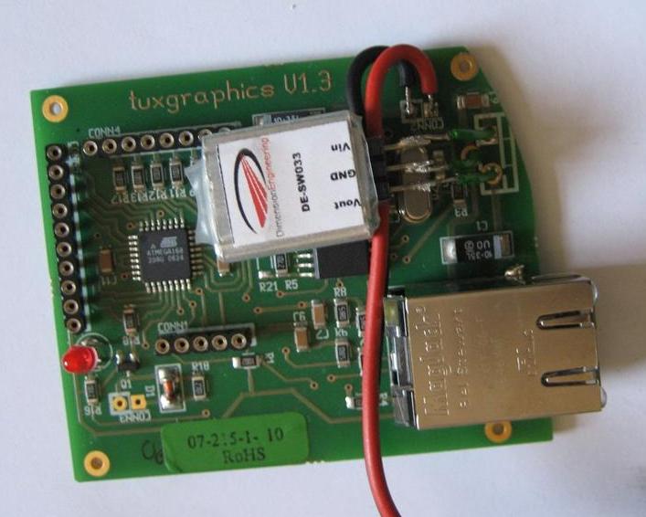 |
| Unmodified lamp. | Base with cut-outs for Ethernet and DC jacks. | Tuxgraphics PCB, fitted with Dimension Engineering regulator. |
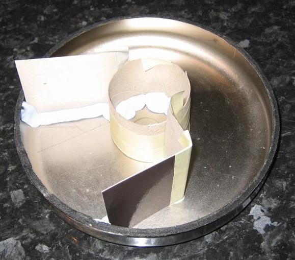
Next I removed the old weight in the base and constructed a dam in the base ready for filling with Plaster of Paris. The dam was constructed from masking tape, glossy card, BlueTak and an old toilet roll inner to give a nice circular section in the centre of the base. I filled as much of the base as I could with a thick Plaster of Paris mix and then left it over night to dry.
 |
 |
 |
| Upturned base with mould. The discarded weight is to the right. | Base mould ready for filling. | Base filled with a thick mixture of Plaster of Paris. |
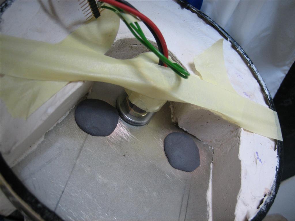
Now the base was weighted, I could install the base circuit board. To do this I outlined the circuit board with a pencil, and marked the fixing holes at each corner of the circuit board. I then roughened up the interior surface of the lamp base and built up mounds of epoxy putty using more masking tape and some clear plastic to protect the central area. I made the mounds a little larger than needed and then pressed the circuit board, wrapped in cling film, into the putty before it was fully cured. This allowed me to ensure good alignment between the Ethernet jack and the cut-outs, positioning it carefully to best align against the slightly curved outer edge of the base. Setting the board into the putty also helps the board to resist any insertion force when and Ethernet jack is inserted as the board pushes back against the cured putty. Finally I drilled and tapped holes in the putty and used some tiny screws to fix the board.
 |
 |
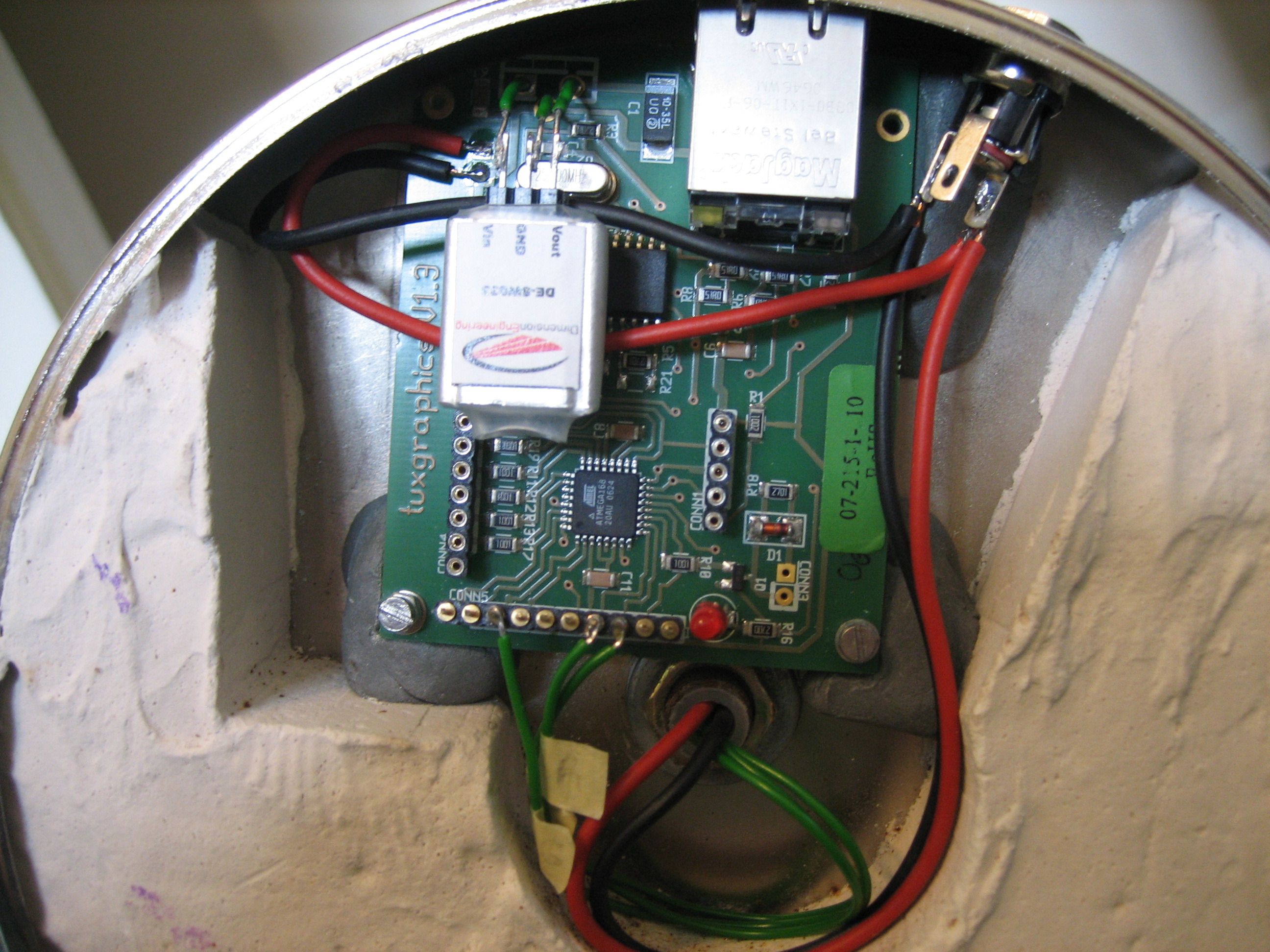 |
| Building up epoxy mounts to seat the circuit board. Note the making to protect the central area. | Base with circuit board installed on epoxy mounds. | Close up of base showing circuit board set into epoxy. Note the filed corner of the PCB. |
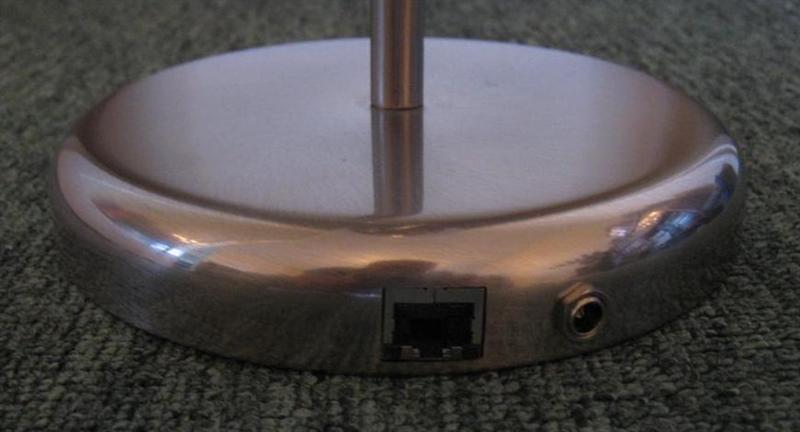 |
| Base with jacks installed in cut-outs. |
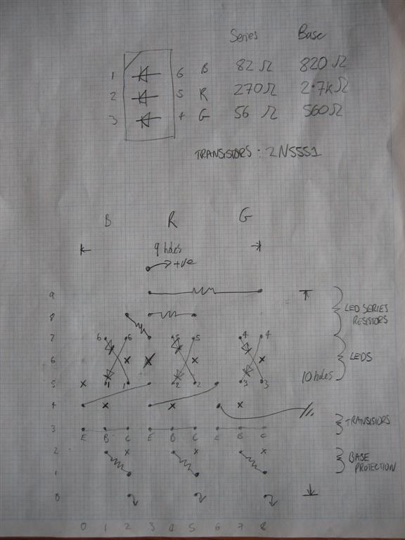
The only thing left to do now was to build and mount the top circuit. I'd already removed the screw lightbulb fitting from the top of the lamp and using a junior hacksaw I was able to make two slots in the plastic. I'd designed the top circuit to be narrow enough to fit inside this part of the lamp (9x10 holes), but assembled the circuit on a little extra strip board so that it could be slotted into the plastic 'holder'. Once I was happy that the circuit fitted correctly, I pulled 5 wires through the lamp's stem, two slightly thicker for positive and negative, and 3 thinner wires for LED control. I then reused some protective cloth tubes from the original lamp to protect the wires from stripping, and soldered them onto the circuit board. Carefully I then pulled the wires through the lamp's stem and guided the top circuit into the slots I'd cut. Once it was well positioned I added a pair of small rubber bands to hold the circuit into the slots and connected the other ends of the wires to the base circuit.
 |
 |
 |
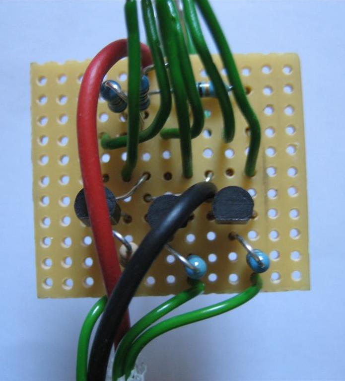
| Design for the LED driver circuit on breadboard (9x10 holes). | Component side of the LED driver circuit. | Backside of the LED driver circuit. (13x11 holes) |
 |
 |
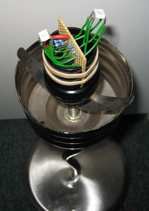 |
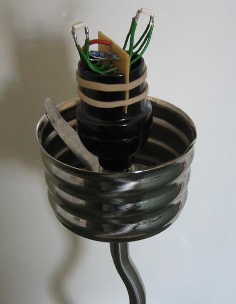
| Close up of circuit in same orientation as schematic. | Top circuit mounted and secured with two rubber bands. The large metal 'spring' holds the glass lamp cover when installed. | Alternative view. Note the LEDs soldered on stiff wire from both sides of the strip board. |
And that's it! The device is done, and with the software loaded, it can be plugged into 9 volts DC and Ethernet, and is ready to rock!
 |
 |
 |
 |
| Full red. | Full green. | Full blue. | Lamp off. |
| Video of a slow colour fade sequence. |
Having to compile and download C code in order to generate a command sequence for the device is not ideal. Therefore I made a few helper programs to allow varying degrees of device control. These are detailed in the following sections.
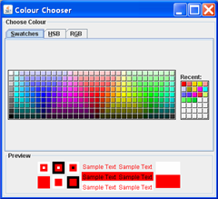
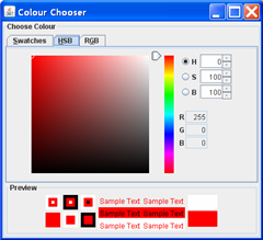
This was the first client program, and was hastily adapted from Sun's ColorChooserDemo. It simply displays a colour palette, and allows you to select a colour. In the background it resolves the device name, 'lightbulb', to an IP address and constructs colour commands that are sent to the device.
 |
 |
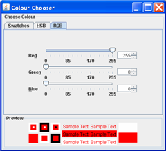 |
This little app is great for trying to get a specific colour to be displayed. While the colours in the palette don't always exactly match the actual output (for example, black in the picker resolves to the light being fully off), the RGB picker can be quickly used to fine tune the output to get the exact value required. In itself this still doesn't allow for autonomous control of the device, but is a great tool when selecting colours.
This is the most powerful client. It parses a text file containing device commands and produces the appropriate binary bytes for the device. It can therefore be used in a couple of ways, either by generating output for sending directly to the device, or as a part of a cgi-script to return instruction sequences in response to a request made by some device.
The input to cmdforge is a text file with commands, comments or labels on each line. The following table describes the allowable commands that can be used to make up complicated sequences of light changes.
| Input line | Meaning | |
|---|---|---|
| # Blah | A comment line. | |
| :label | Define a label named label. | |
| c ms r g b | Change to some colour over a period of ms milliseconds, where ms must be in the range of 0-4064. If ms is 0, change immediately. | |
| stop | Stop executing the current command sequence. | |
| jump signedoffset | Relative jump of some count of bytes, which must be between -128 and +127. If the count is 0, this is the same as a stop command | |
| jump :label | Jump to some label and continue execution there. Again, the label must be within -128 and +127 bytes of the current instruction with a jump to itself being the same as the stop command. | |
| delayms ms | Sleep for ms milliseconds, maintaining light output. | |
| delaysec sec | Sleep for sec seconds, maintaining light output. sec must be in the range of 0-4095. | |
| ack id | Send a UDP acknowledgement carrying the 8-bit id to the last host to upload a command sequence to the device. This is sent back to port from which the command sequence originated. | |
| fetch url | Cmdforge looks up the IP address for the host, and then encodes the IP address into the instruction. The device then establishes an HTTP connection to the host and requests the page. If successful, the response replaces the currently executing sequence. If the host cannot be contacted or the response is invalid, the current sequence continues to execute. | |
| load reg val | Set register reg to the unsigned 8-bit value val. | |
| add reg val | Add the 5-bit unsigned value val to reg. | |
| dec reg val | Subtract the 5-bit unsigned value val from reg. | |
| stopze reg | Stop sequencer execution if reg holds a value of zero. | |
| jumpze reg offset | Take a relative jump of offset bytes if reg holds a value of zero. The offset must be in the range of -128 to +127. An offset of 0 behaves the same as stopze. | |
| jumpze reg :label | Jump to label bytes if reg hold a value of zero. Again, the label must be within -128 and +127 bytes of the current instruction, and behaves as stopze if the jump is to the same instruction. | |
| predef cmd | Stop current sequencer and run the predefined command sequence cmd from EEPROM. If no such command sequence is defined, this does nothing. cmd must be in the range of 0-31. |
Table 3: Cmdforge input syntax.
By default there are 4 registers defined, a, b, c and d, allowing for complex loops to be created through the jumpze and stopze operations, as shown in listing 4.
# Pulse red for 10 seconds
load a 10
:start
c 0   0   0   0
c 500 255 0   0
c 500 0   0   0
stopze a
jump :start
Listing 7: Cmdforge input
The predef instruction allows for pre-programmed command sequences to be loaded and executed from the device's EEPROM. The device normally utilises 8 pre-defined sequences, enumerated in eprom.h, although more can be defined if required.
Cmdforge also allows the pre-defined sequences to be updated without the use of an external programmer by passing it an appropriate script and ran with the -eeprom option. In this mode it generates an extra vector ahead of the normal output, such that the output is in the EEPROM format required by my firmware (which is literally just a structure defined in eprom.h). The input script must contain labels for each of the predefined sequences, such as ":pdPost" and ":pdEthUp", as well as any number of ":pdUsr0" labels for user defined scripts. An example EEPROM script is given here.
Cmdforge itself doesn't generate UDP packets, but under BASH, command sequences can be sent to the device very simply by using redirection to the specially interpreted /dev/udp pseudo-filesystem. Normal command sequences are sent to port 8888, while EEPROM images are sent to 8889, noting that the EEPROM is only allowed to be reprogrammed for 10 seconds after the device is switched on and initially configured. Listing 8 shows different ways of calling cmdforge to send packets to the device.
$ cmdforge in.cmd - > /dev/udp/lightbulb/8888
$ cat in.cmd | cmdforge - - > /dev/udp/lightbulb/8888
$ cmdforge -eeprom in - > /dev/udp/lightbulb/8889
Listing 8: Various commands for sending light sequences to a device named 'lightbulb'.
Cmdforge can also be used in CGI scripts to output sequences in response to device requests. The following example shows how I've done this, using a shell script.
#!/bin/bash
echo "Content-Type: application/octet-stream"
echo
echo "c 4000 0 0 255" | cmdforge - -
Listing 9: Using cmdforge to return data in a CGI script.
| Short video of the heartbeat sequence. |
This is a fun little program that runs on a Linux system and monitors the system uptime and IO load. It periodically sends commands to the light device to cause it to pulse its output in a similar manner to a heartbeat. The colour ranges from green to orange to yellow based on CPU usage, while the speed changes between 20 and 60 beats per second in response to IO load. The device expects to be sent a new command sequence every 10 seconds, otherwise it stops beating and slowly turns blue if no command is received for more than 20 seconds.
Ideally this program should really make use of the ack sequence command and similarly check that the device is responding to each update to be doubly certain that the correct status is being show. Maybe I will make that enhancement at some point.
The classic application for this type of device is to tell you the weather forecast (the other one seems to be stock portfolios). I felt the project couldn't be complete without implementing this application myself, so decided to knock one together.
The first problem is where to source a weather forecast. As a TV licence fee payer, I decided that the BBC weather page would be a good place, and checking their robots.txt file I could see that it wasn't banned from automatic fetching. Wget can be used to easily grab the page when needed, but I needed a way to extract the required fields. Researching how best to do this it appeared that an X3C standard named XPath allows XML documents to be navigated and for subsets to be selected through a simple expression language.
In theory XPath should have solved the problem, but I was immediately struck with the problem that HTML is rarely valid XML and so needs cleaning up before parsing. Tagsoup looked like a solution and I was quickly able to load HTML documents into Java. Then I needed a Java XPath implementation, and this is where I found myself fairly disappointed; there are multiple implementations, each with their own idiosyncrasies, all seemingly difficult to make work with other parsers. I did eventually get this working, using Tagsoup and JDom's XPath implementation, but found that I had to use namespaces in the XPaths. This made an otherwise simple syntax somewhat verbose and fiddly, and searching the web there seemed to be no easy way to disable this (as others had found, disabling the namespace option in Tagsoup didn't work; I suspect the JDom SaxParser was forcing namespaces). In the end I wrote a few lines of code to strip the namespaces from the document tree, and I could now use simpler XPath expression. Unfortunately it was at this point that I found the XPath implementation didn't support the 'id()' function. Normally I really like Java programming, but in this case it really was painful and I decided to find a better approach. (The aborted software is available in the download section should it help anyone else).
I did find that PHP5 had a simple method of loading HTML and running it against an XPath, and started looking at that. However, my ISP only has PHP4 which doesn't provide the same functionality. Scratching a little deeper it looks as though the PHP implementation merely wraps libxml2, a library with an easy enough C API to load HTML and evaluate XPath expressions, and with a fully complete XPath implementation. I therefore wrote a small C program called scrape to allow processing of an HTML document through an XPath.
$ wget --output-document=weather.html www.bbc.co.uk/weather/
--20:18:29--  http://www.bbc.co.uk/weather/
           => `weather.html'
Resolving www.bbc.co.uk... 212.58.251.201
Connecting to www.bbc.co.uk|212.58.251.201|:80... connected.
HTTP request sent, awaiting response... 200 OK
Length: unspecified [text/html]

    [       <=>                           ] 24,356         4.66K/s

20:18:34 (4.66 KB/s) - `weather.html' saved [24356]
$ scrape weather.html "id('day1sym')/center/img/@src"
<src>weather_files/10.gif</src>
$ scrape weather.html "id('day1txt')/h3/text()"
24
Listing 10: Fetching a complex HTML document and extracting information using libxml2 to parsing and XPath.
This small program makes it trivial to pull data out of complex HTML using XPaths as can be seen in listing 7, whereby the weather symbol and days temperature is extracted. For the BBC weather, this is made even easier by the fact that their HTML is well marked up such that the id function can quickly find the correct document sub-tree, which is very close to the desired data.
Using scrape, I've constructed a CGI script that extracts the weather and produces a light command sequence via cmdforge. The script is on my ISPs server and returns the human readable light sequence if no arguments are passed to it. If a single argument is passed, it returns the binary format.
cmdforge.